- 您现在的位置:买卖IC网 > Sheet目录2011 > MAX5893EGK+D (Maxim Integrated Products)IC DAC 12BIT DUAL 500MSPS 68-QFN
MAX5893
12-Bit, 500Msps Interpolating and Modulating
Dual DAC with CMOS Inputs
12
______________________________________________________________________________________
Detailed Description
The MAX5893 dual, 500Msps, high-speed, 12-bit, cur-
rent-output DAC provides superior performance in
communication systems requiring low-distortion ana-
log-signal reconstruction. The MAX5893 combines two
DAC cores with 8x/4x/2x/1x programmable digital inter-
polation filters, a digital quadrature modulator, an SPI-
compatible serial interface for programming the device,
and an on-chip 1.20V reference. The full-scale output
current range is programmable from 2mA to 20mA to
optimize power dissipation and gain control.
Each channel contains three selectable interpolating fil-
ters making the MAX5893 capable of 1x, 2x, 4x, or 8x
interpolation, which allows for low-input and high-out-
put data rates. When operating in 8x interpolation
mode, the interpolator increases the DAC conversion
rate by a factor of eight, providing an eight-fold
increase in separation between the reconstructed
waveform spectrum and its first image. The MAX5893
accepts either two’s complement or offset binary input
data format and can operate from either a single- or
dual-port input bus.
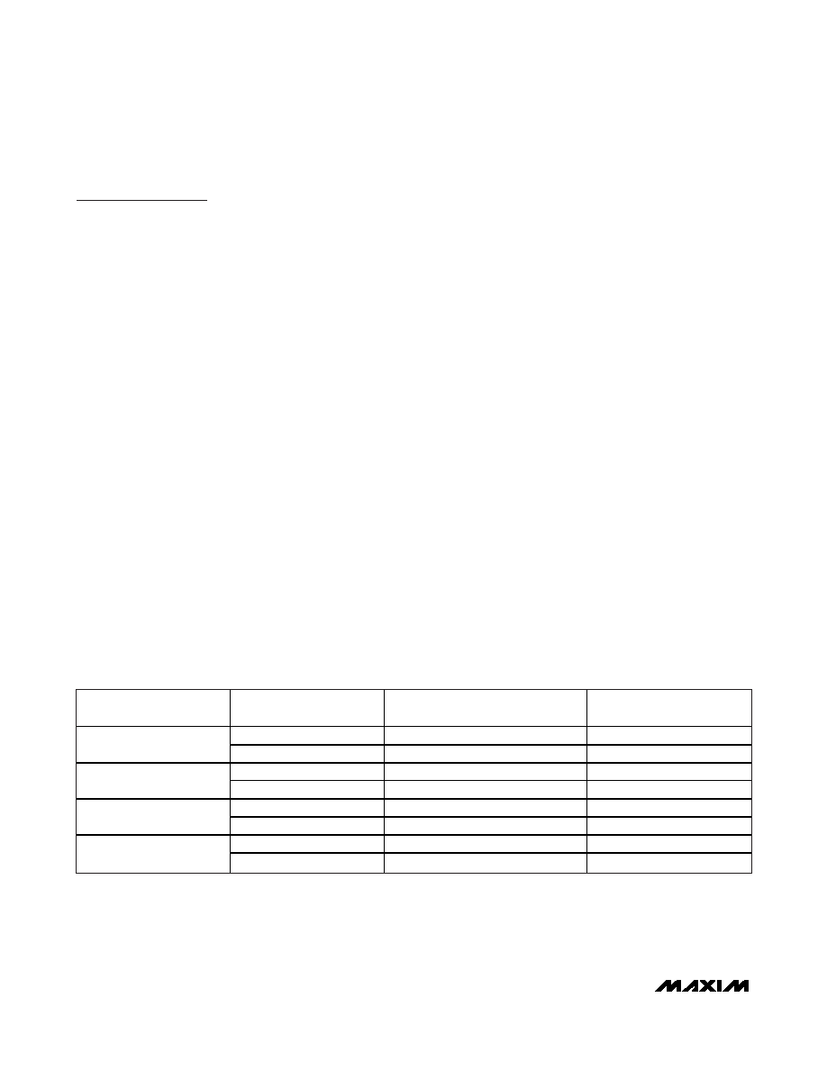
The MAX5893 includes modulation modes at fIM/2 and
fIM/4, where fIM is the data rate at the input of the modu-
lator. If 2x interpolation is used, this data rate is 2x the
input data rate. If 4x or 8x interpolation is used, this data
rate is 4x the input data rate. Table 1 summarizes the
modulator operating data rates for dual-port mode.
The power-down modes can be used to turn off each
DAC’s output current or the entire digital section.
Programming both DACs into power-down simultane-
ously will automatically power down the digital interpo-
lator filters. Note the SPI section is always active.
The analog and digital sections of the MAX5893 have
separate power-supply inputs (AVDD3.3, AVDD1.8,
AVCLK, DVDD3.3, and DVDD1.8), which minimize noise
coupling from one supply to the other. AVDD1.8 and
DVDD1.8 operate from a typical 1.8V supply, and all
other supply inputs operate from a typical 3.3V supply.
Serial Interface
The SPI-compatible serial interface programs the
MAX5893 registers. The serial interface consists of the
CS, SDI, SCLK, and SDO. Data is shifted into SDI on
the rising edge of the SCLK when CS is low. When CS
is high, data presented at SDI is ignored and SDO is in
high-impedance mode. Note:
CS must transition high
after each read/write operation. SDO is the serial data
output for reading registers to facilitate easy debug-
ging during development. SDI and SDO can be con-
nected together to form a 3-wire serial interface bus or
remain separate and form a 4-wire SPI bus.
The serial interface supports two-byte transfer in a
communication cycle. The first byte is a control byte
written to the MAX5893 only. The second byte is a data
byte and can be written to or read from the MAX5893.
Table 1. Quadrature Modulator Operating Data Rates (fIM is the Data Rate at the Input of
the Modulator) for Dual-Port Mode
INTERPOLATION RATE
MODULATION MODE (fLO)
MODULATION FREQUENCY
RELATIVE TO fDAC
MODULATION FREQUENCY
RELATIVE TO fDATA
fIM/2
fDAC/2
fDATA/2
1x
fIM/4
fDAC/4
fDATA/4
fIM/2
fDAC/2
fDATA
2x
fIM/4
fDAC/4
fDATA/2
fIM/2
fDAC/2
2 x fDATA
4x
fIM/4
fDAC/4
fDATA
fIM/2
fDAC/4
2 x fDATA
8x
fIM/4
fDAC/8
fDATA
发布紧急采购,3分钟左右您将得到回复。
相关PDF资料
MAX5894EGK+D
IC DAC 14BIT DUAL 500MSPS 68-QFN
MAX5895EGK+D
IC DAC 16BIT 500MSPS DUAL 68-QFN
MAX5898EGK+D
IC DAC 16BIT DUAL 500MSPS 68-QFN
MAX6900ETT+T
IC RTC I2C COMPAT 6-TDFN
MAX6902ETA+T
IC RTC SPI COMPAT 8-TDFN
MAX7375AXR604+T
IC OSC SILICON SC70-3
MAX7394ATTLY+T
IC OSC SILICON 922KHZ 6-TDFN
MAX7403CSA+
IC FILTER LOWPASS 8-SOIC
相关代理商/技术参数
MAX5893EGK+TD
功能描述:数模转换器- DAC 12-Bit 2Ch 500Msps DAC RoHS:否 制造商:Texas Instruments 转换器数量:1 DAC 输出端数量:1 转换速率:2 MSPs 分辨率:16 bit 接口类型:QSPI, SPI, Serial (3-Wire, Microwire) 稳定时间:1 us 最大工作温度:+ 85 C 安装风格:SMD/SMT 封装 / 箱体:SOIC-14 封装:Tube
MAX5893EGK-D
功能描述:数模转换器- DAC RoHS:否 制造商:Texas Instruments 转换器数量:1 DAC 输出端数量:1 转换速率:2 MSPs 分辨率:16 bit 接口类型:QSPI, SPI, Serial (3-Wire, Microwire) 稳定时间:1 us 最大工作温度:+ 85 C 安装风格:SMD/SMT 封装 / 箱体:SOIC-14 封装:Tube
MAX5893EGK-TD
功能描述:数模转换器- DAC RoHS:否 制造商:Texas Instruments 转换器数量:1 DAC 输出端数量:1 转换速率:2 MSPs 分辨率:16 bit 接口类型:QSPI, SPI, Serial (3-Wire, Microwire) 稳定时间:1 us 最大工作温度:+ 85 C 安装风格:SMD/SMT 封装 / 箱体:SOIC-14 封装:Tube
MAX5893EVCMOD2
功能描述:数模转换器- DAC Evaluation Kit for the MAX5893/MAX5894/MAX5895 RoHS:否 制造商:Texas Instruments 转换器数量:1 DAC 输出端数量:1 转换速率:2 MSPs 分辨率:16 bit 接口类型:QSPI, SPI, Serial (3-Wire, Microwire) 稳定时间:1 us 最大工作温度:+ 85 C 安装风格:SMD/SMT 封装 / 箱体:SOIC-14 封装:Tube
MAX5893EVKIT
功能描述:数模转换器- DAC Evaluation Kit for the MAX5893/MAX5894/MAX5895 RoHS:否 制造商:Texas Instruments 转换器数量:1 DAC 输出端数量:1 转换速率:2 MSPs 分辨率:16 bit 接口类型:QSPI, SPI, Serial (3-Wire, Microwire) 稳定时间:1 us 最大工作温度:+ 85 C 安装风格:SMD/SMT 封装 / 箱体:SOIC-14 封装:Tube
MAX5894EGK+D
功能描述:数模转换器- DAC 14-Bit 2Ch 500Msps DAC RoHS:否 制造商:Texas Instruments 转换器数量:1 DAC 输出端数量:1 转换速率:2 MSPs 分辨率:16 bit 接口类型:QSPI, SPI, Serial (3-Wire, Microwire) 稳定时间:1 us 最大工作温度:+ 85 C 安装风格:SMD/SMT 封装 / 箱体:SOIC-14 封装:Tube
MAX5894EGK+TD
功能描述:数模转换器- DAC 14-Bit 2Ch 500Msps DAC RoHS:否 制造商:Texas Instruments 转换器数量:1 DAC 输出端数量:1 转换速率:2 MSPs 分辨率:16 bit 接口类型:QSPI, SPI, Serial (3-Wire, Microwire) 稳定时间:1 us 最大工作温度:+ 85 C 安装风格:SMD/SMT 封装 / 箱体:SOIC-14 封装:Tube
MAX5894EGK-D
功能描述:数模转换器- DAC RoHS:否 制造商:Texas Instruments 转换器数量:1 DAC 输出端数量:1 转换速率:2 MSPs 分辨率:16 bit 接口类型:QSPI, SPI, Serial (3-Wire, Microwire) 稳定时间:1 us 最大工作温度:+ 85 C 安装风格:SMD/SMT 封装 / 箱体:SOIC-14 封装:Tube